Magnetic loops
I am not going to explain the theory of this antenna since it is very well described in literature and on many web sites (see my links page) but, more practically, I would like to give here an overview of the successful designs I have tested and some useful tricks.
However, just as a short introduction, I would like to remind the key characteristics about these antennas since they are quite different to other more common antennas such as dipoles, verticals, etc and because knowing these differences can help in using them better:
-
Magnetic component of the electromagnetic field: impact on noise pick-up
-
shape of radiation pattern : think about it when implementing it
-
High Q and narrow bandwidth are tighten together, one is desirable (high Q) as it provides to this type of antenna its characteristic efficiency, the other one (narrow bandwidth) is one of the consequences of the high Q but we can learn to live with it !
Based on these characteristics, one needs to understand that, under specific circumstances, they can achieve a better efficiency as compared to a classic dipole or a vertical antenna, for example when it is not possible to implement a good grounding system and/or when the space to put a full size antenna is not available. An interesting comparison for example can be: how a magnetic loop can compare with a mobile shortened antenna on a balcony ? To be honest, the answer is not simple, we need to think about bandwidth (frequency can be changed in case of a remote loop), efficiency, available ground system in case of the vertical wipe, etc…and you can reach different conclusions based on different operator wishes, bands and locations.
There are various situations in which these antennas can be tried and used so I think helpful to indicate first that my interest in these antennas have mainly been to achieve a multiband system that can be used in an apartment either indoor or on the window or balcony, not a fully remote system since it keeps being accessible by hand from time to time, for example to change from one band to another: this can explain the sizes and technical choices I have made.
Primary loop
Nothing special to say about the loop itself except that its diameter determines the usable frequency range and the diameter of the tube section used to build the loop h as major impact on its radiating efficiency. Note also that the loop can be made with a copper or aluminium ribbon instead of a tube (in that case, you can replace the perimeter by two times the width of the ribbon in the formulas); in fact, the shape of the conductor does not matter much, what is critical is to provide the biggest apparent diameter or exposed surface for this conductor. Whatever you can use, try to go to the biggest diameter (or width in case of a ribbon) you can achieve knowing that there are obvious limitations in term of weight, mechanical resistance and cost !
Feeding the main loop
There are many ways to feed a magnetic loop (gamma match, tuning variable capacitor, secondary loop and possibly others).
-
The coupling loop (secondary loop): I have tested several, but in my quest of multiband loops, the best I have found is the secondary loop, sometimes called the Farraday loop, so all the loops you will see on this page are based on this design. The coupling loop I use is made of RG-58 coaxial according to the following schematic:
-
Gamma match: it may be found easier to build and tune and it is certainly the perfect choice for a monoband loop but, to my experience, it is not suitable for a multiband use.
-
The tuning variable capacitor is fine for multiband use but more complex to build since it requires two variable capacitors with appropriate voltage rating. It means also two driving motors in case of a remote antenna. However, this can be a valuable option for a portable loop dedicated to a QRP transmitter since you can easilly get access to the variable capacitors for manual tuning.
click on image to enlarge
Some loop examples
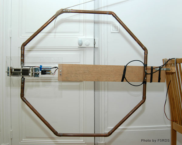
80 cm diameter loop for 20 to 10 meter bands
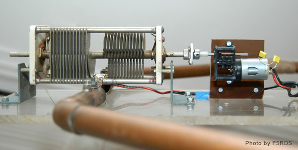
This loop is an octogone in copper tubing of 22 mm diameter equipped with a split stator variable capacitor.
160 cm diameter loop for 40 to 20 meter bands
This loop is made from RG-8 coaxial and is tuned with one CV for band switching and a second CV for band tuning. I deliberately took advantage of the softness of the coaxial in the lower part to twist the loop to move it out of the window into its operating position, something that would not have been possible with a rigid loop. Furthermore, the two arms in V position can be folded on the boom and the loop can be folded for storage. Not very nice but very handy !
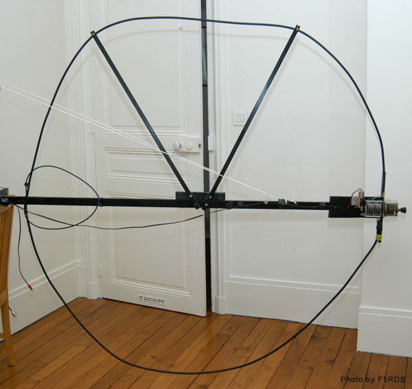
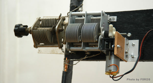
Both loops are remotely tuned with DC motors and appropriate reduction gear.
The two loops have mostly been used either in indoor or attached in a vertical position just as on the pictures on an apartment window, hanging outside, for the curriosity of my neighborgs !
Various tricks
-
Reduce losses: solder everything to keep high Q
-
double variable capacitor to tune multibands : one variable capacitor of about 10 pF to tune within a given band and in parallel a variable capacitor of 150 pF to move from one band to another
-
various variable capacitor configurations : butterfly, pumping variable capacitor, variable capacitor with sliding copper or aluminium foils
-
simple fixed capacitor :when necessary in parallel to the variable capacitor, a fixed capacitor with high voltage insulation can be built with separated plates made from printed circuit boad cut at the appropriate size and maintained at a fixed distance or appropriate lenghts of coax cable like RG-8 (RG-58 not suitable due to lower voltage insulation)
-
loop position matters: try to keep them at least half diameter (or even one diameter) away from ground and from magnetic structure. Use vertical position when close to ground. Horizontal position can be used for omnidirectional patern if the loop is high enough (0.25 to 0.5 lembda)
-
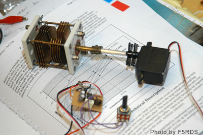
remote variable capacitor requires an accurate and reproducible driving system. DC motors with pulse control circuit and reduction gear are doing a great job at this and are quite simple to build. Stepper motors are much more complex to use and not so often selected by home builders (but more frequently used on commercial models). Sservo control used for radiocontrol models can be an interesting alternative solution. Below is just what I am currently testing for my next loop.
Some calculations
Here is below a link to an Excel spreadsheet that I have developed based on classic formulas published in litterature. I designed this very simple spreadsheet to generate performance parameters of a given design on multiple bands at one time, which helps to accelerate quite a bit the various modelling and testing. The only information you need to enter are the diameter of the main loop and the diameter of the tube you plan to use for the main loop. The spreadsheet calculates the main performance parameters for the most common Ham bands but you can change the frequencies as needed. It also gives you the best size of the secondary loop and the upper usable frequency (based on the inductance and capacity of the main loop).
F5RDS magnetic loop spreadsheet
Using this spreadsheet, I have computed and summarized in the table below some design efficiencies just to give an idea of comparative performance between them.
| main loop diam. (cm) | conductor diam. (mm) | material | Radiating power efficiency (%) / Loss relative to a loss-less antenna (dB) | ||||
|---|---|---|---|---|---|---|---|
| 10 m | 15 m | 20 m | 30 m | 40 m | |||
| 80 | 10 | RG-8 | 85% / -0.7 dB | 67% / -1.8 dB | 33% / -4.8 dB | 13% / -8.8 dB | 4.1% / -14 dB |
| 20 | copper tube 20 mm | 92% / -0.36 dB | 80% / -0.96 dB | 49% / -3.0 dB | 23% / -6.4 dB | 8 % / -11 dB | |
| 30 | copper tube 30 mm | 90% / -0.44 dB | 86% / -0.66 dB | 59% / -2.3 dB | 31% / -5.1 dB | 11% / -9.4 dB | |
| 100 | 10 | RG-8 | 92% / -0.37 dB | 80% / -0.98 dB | 49% / -3.1 dB | 23% / -6.4 dB | 7.7% / -11 dB |
| 20 | copper tube 20 mm | 96% / -0.19 dB | 89% / -0.52 dB | 66% / -1.8 dB | 37% / -4.3 dB | 14% / -8.4 dB | |
| 30 | copper tube 30 mm | 95% / -0.13 dB | 92% / -0.35 dB | 74% / -1.3 dB | 47% / -3.3 dB | 20% / -7.0 dB | |
| 120 | 10 | RG-8 | can't work - max 26 MHz | 87% / -0.59 dB | 62% / -2.1 dB | 34% / -4.7 dB | 13% / -9.0 dB |
| 20 | copper tube 20 mm | can't work - max 28 MHz | 93% / -0.31 dB | 77% / -1.2 dB | 51% / -3.0 dB | 23% / 6-.5 dB | |
| 30 | copper tube 30 mm | LIMIT 29.7 MHz | 95% / -0.21 dB | 83% / -0.8 dB | 61% / -2.2 dB | 30% / -5.2 dB | |
| 160 | 10 | RG-8 | can't work - max 19 MHz | can't work - max 19 MHz | 80% / -0.99 dB | 55% / -2.6 dB | 26% / -5.9 dB |
| 20 | copper tube 20 mm | can't work - max 20.3 MHz | can't work - max 20.3 MHz | 89% / -0.52 dB | 71% / -1.5 dB | 41% / -3.9 dB | |
| 30 | copper tube 30 mm | can't work - max 21.4 MHz | can't work - max 21.4 MHz | 92% / -0.38 dB | 78% / -1.1 dB | 51% / -2.9 dB | |
As a conclusion, I would like to say that these loop antennas have allowed me to be active on some bands in locations where the other types of antenna I tried failed. As always in real life, things are never completely black or white, but with a wide variety of gray nuances, so these magnetic loops are not the only possible answer to all situations and issues, otherwise everyone would be using them today ! If you are enough lucky to live in an area where you can put large, full size antennas, you don’t really need them; why would you bother with such narrow bandwidth for example ? But if you are facing antenna restrictions or lack of space on your roof, if you want to put your antenna on your balcony, or if you plan some portable operations without deployed long wires and carrying long masts, or even for the fun of experimenting new things, I encourage you to give it a try, you will be surprised to see that, yes, they work !!!

