
Log periodic 4 elements
 When deciding it was time to replace my homemade 4 elements 10 meters
beam by a new directive antenna, I was expecting a type of antenna that
would allow me to be active on
multiple bands, ideally from 10 to 20 meters; and it had to be a
homemade project. I had a large glance at all possible types of
multiband directives in multiple documentation and technical
litterature.
When deciding it was time to replace my homemade 4 elements 10 meters
beam by a new directive antenna, I was expecting a type of antenna that
would allow me to be active on
multiple bands, ideally from 10 to 20 meters; and it had to be a
homemade project. I had a large glance at all possible types of
multiband directives in multiple documentation and technical
litterature.
The quad type appeared a good option but was not possible to implement because the antenna had to be placed on the roof on a small mast since I did not own a tower.
A trapped yagi was not an option for me, mainly due to the mechanics of the traps.
Finally, the log periodic dipole array (LPDA) appeared a very interesting design since it would opened to me the possibility to access to more bands as compared to a classical tribander design.
The ARRL antenna book was my main source of information to elaborate a prototype. Obviously, based on the gain, the 12 elements was the best to build. However, the size of this antenna (almost as large as the house roof itself) and my main limitation being this small mast, I had to make a tough compromise and my 12 elements turned more realistically into a 4 elements design. The 4 elements were calculated to be part of a 8 element design, in case I could build it in future times.
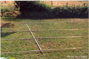
Dimensions and anticipated gain
design parameter Tau : 0.73
sizes from the shortest to the longest element :
elm1 = 4.02 m
elm2 = 5.52 m
elm3 = 7.57 m
elm4 = 10.38 m
distance from elm1 to elm2 = 1.39m
distance from elm2 to elm3 = 1.91 m
distance from elm3 to elm4 = 2.62 m
boom lenght : 5.92 m
homemade balun 4:1 ratio with a T-200 between the 50 ohms coaxial line and the periodic line in front of the antenna.
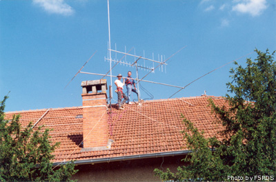
Here are some pictures taken while installing the antenna on the roof with a good friend of mine, Eric, SWL and vintage Ham gear collector.
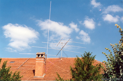
The log periodic beam with the two yagi beams for VHF (2x9 elements) and UHF (21 elements). In front of it, the vertical antenna is a the Gotam that I used at that time for all bands from 40 to 10 m.
Antenna efficiency
Here are below some simulations that I performed on NMMA with this antenna design.
|
14 MHz band |
14 MHz band |
 28 MHz band |
 28 MHz band |
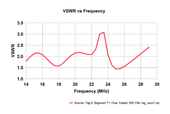 SWR plot from 14 MHz to 30 MHz |


(click on each picture to enlarge)
The simulations are always good at anticipating the possible performance parameters of an antenna but real life is more important. During the period I have been using this antenna, I have made the following observations:
- directivity was marked mainly on 10 and 15 m and was less evident on 20m.
- Front to back ratio was more evident on higher bands as well, not very surprising when considering the design.
- The ROS was good on all bands between 20 to 10 m including WARC bands, consistently close or below 2:1, which was what I primarily wanted.
Overall, a lot of contacts were made with this antenna, very easy to use, a wide band coverage but limited gain as well. A good compromize for someone who wants an easy access to 5 bands for a minimum effort of building and reduced size on the roof, when not having a tower. With no doubts, the 12 elements design is certainlty THE design to build to achieve a much better gain and front to back ratio while keeping the wide band corevage feature, but that is a different story in term of size, weight, wind load and QSJ !
I have been using this antenna during several years, but during summer 1999, a stronger wind that usual bent the mast and the antenna felt on the roof. Most of the elements were bent, as well as the boom. I could have repaired it but thought that I had played enough with it and started again to think about a new design.